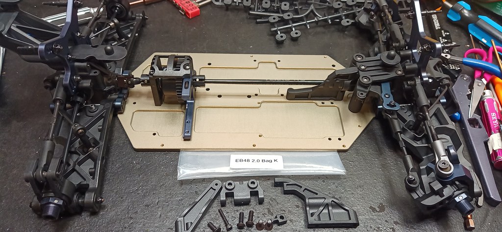
• Welcome to Tekno RC Forums! Are you a Tekno RC fan? If so you're in luck as you've have arrived to the biggest and best Tekno RC community.

    Come join our community and ask your questions, show off your Tekno RCs and share your experience!

BUILD/REVIEW EB48 2.0

This site may earn a commission from merchant affiliate
links, including eBay, Amazon, and others.
K BAG:

Not sure I like the mix of screws here, having to swap between 2.0mm and 2.5mm bits to pull the gear boxes might be annoying, I guess it will all depend on how easily I can remove the bearings from the center shaft locations, hopefully leaving the lower gear box in place... we will soon see when I do my first rebuild, more to come!

50343950306_5594d664a1_b.jpg
 
L BAG:

Here are the upgrades I have decided to go with for this step:
50343955421_57020b00f1_b.jpg


I believe the box stock setup is for bumpy/loamy tracks with emulsion, but I will be racing on a smooth hard pack surface which a bladder setup tends to do better. The kit doesn't include any bladders, but I've decided to copy Chris Allison's setup where he used Losi bladders which work, but they are not a perfect fit, the outer diameter of the Losi bladder is a pinch wider, but the Losi bladder has more support so it's less likely to fail and or get sucked into the shock tube so I can see how it's a better designed bladder. The following pic is Losi bladder on left, TEKNO bladder (must buy separately) in the middle and the emulsion seal (not used) included in the kit:

50344337233_b470fde600_b.jpg


Here you can see the difference in diameter of the seals, you just have to stuff the Losi bladder into the cap it a little more carefully no trimming necessary:

50344338348_41af3b0d44_b.jpg


Here is the skewer style method to grease the seals by placing all the parts on the shaft in reverse order before sliding into the cartridge:

50344379368_71c2f6b5af_b.jpg


Note that I am running the Ti coated shafts which are super smooth, I recently had to buy Ti coated shafts for my SCT because that's all they had in stock at the local shop, then I instantly felt how much smoother the car felt around the track, I'll only run the Ti coated shafts on every car from now on, totally worth it!!!


Here is the method I used to adjust the bladder shocks, where I used one thumb width of exposed shock shaft for setting the rebound:


Unused parts from the kit after drilling my own blank pistons with 8x1.3mm holes which do better for smooth pack tracks:

50344154781_729fc205fa_b.jpg
 
Last edited:
M BAG:

Pretty much the same as before, though I couldn't help but notice that the front/rear shocks are almost identical , in fact I am running the same springs on the front/rear, but the rear shock cartridge inserts are longer than the front cartridge pieces, it will be VERY important not to get the front/rear shocks mixed up during rebuilds. I will need to come up with a system to mark/identify the front/rear shocks going forward, more to come on what I decide to do.

50345292652_8f506797cd_b.jpg
 
N BAG + O BAG

I need to combine both these bags together because I feel it is necessary to complete the O BAG before installing the passenger side guard.

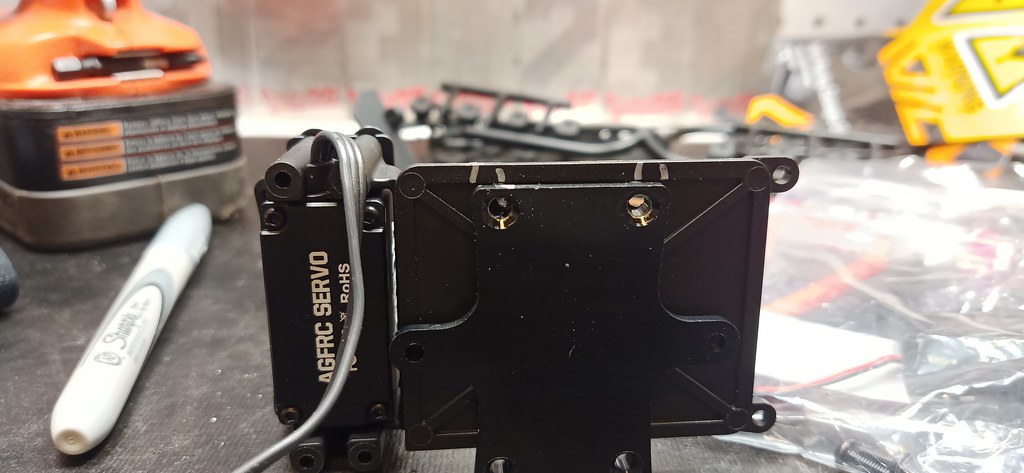
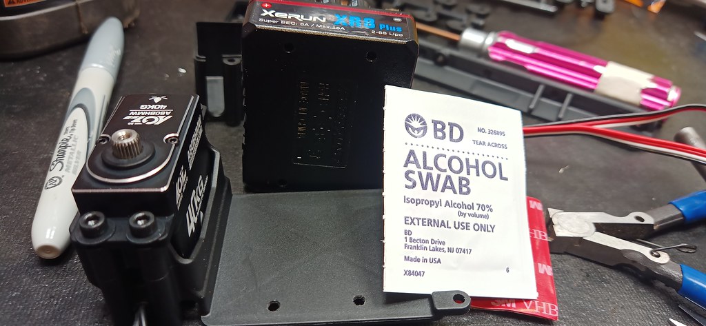
Since there is no way to secure the ESC with zip ties the way the older ESC tray used to work, it will be necessary to screw the ESC in place from under the tray, I used the mounting bracket included with my HobbyWing ESC to help me mark the holes to be drilled. Unfortunately the ESC tray is too small in order to drill all 4 holes the way the manual indicates how the ESC is supposed to be positioned, but at least I can get 2 of the screws to secure the ESC and I think that will be sufficient:

50347608707_bf2360ca2b_b.jpg


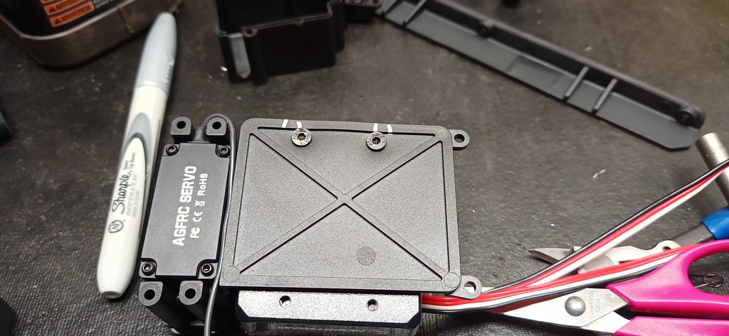
Here you can see the holes I drilled, and I will be using the included 3M tape to secure the ESC taking special care to de-grease both surfaces with an alcohol swab before applying the tape:

50347465101_9fd5a92629_b.jpg


Here you can see that I used the included 2.5mm screws that came with the ESC to mount after carefully aligning the holes while sticking the ESC to the tape:

50347637922_cd63306459_b.jpg


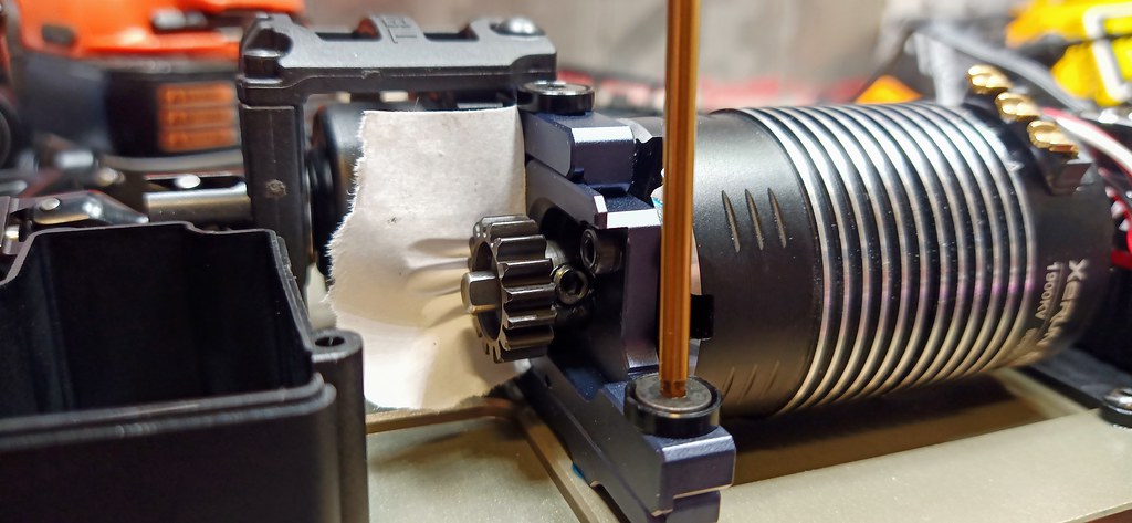
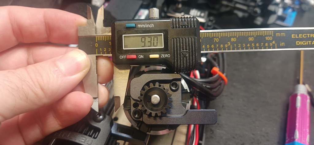
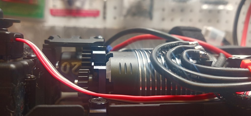
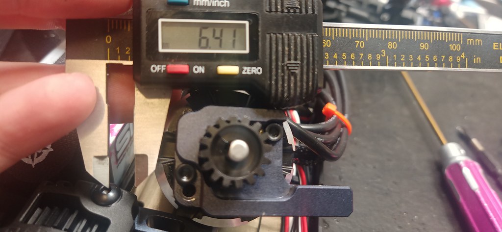
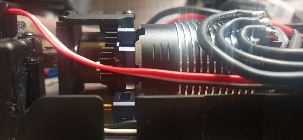
I like to use a piece of paper to set the mesh between the spur and pinion, I actually had to re-set the mesh a second time because there was a high spot on the spur which I placed the paper onto the high spot and re-set the mesh properly:

50346832063_44cf996d21_b.jpg


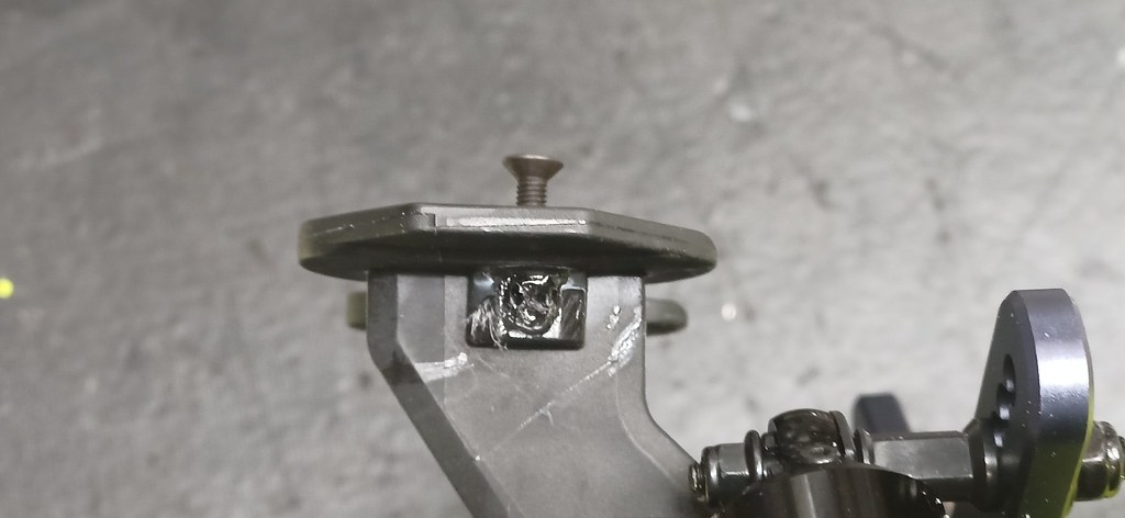
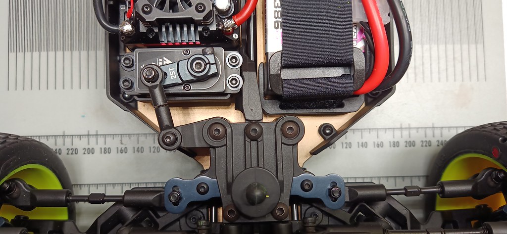
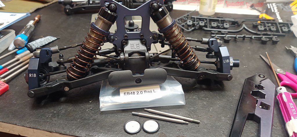
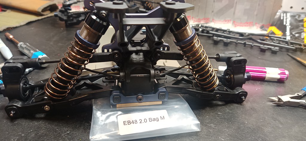
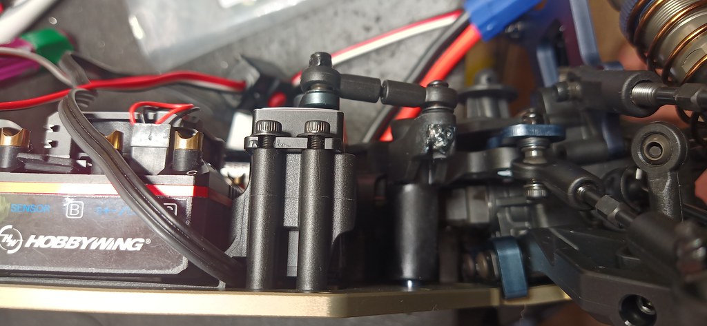
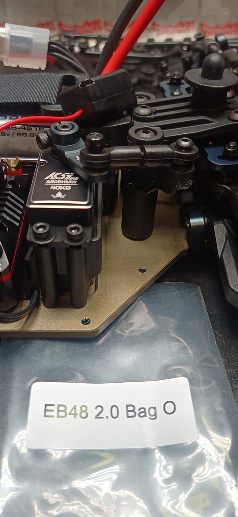
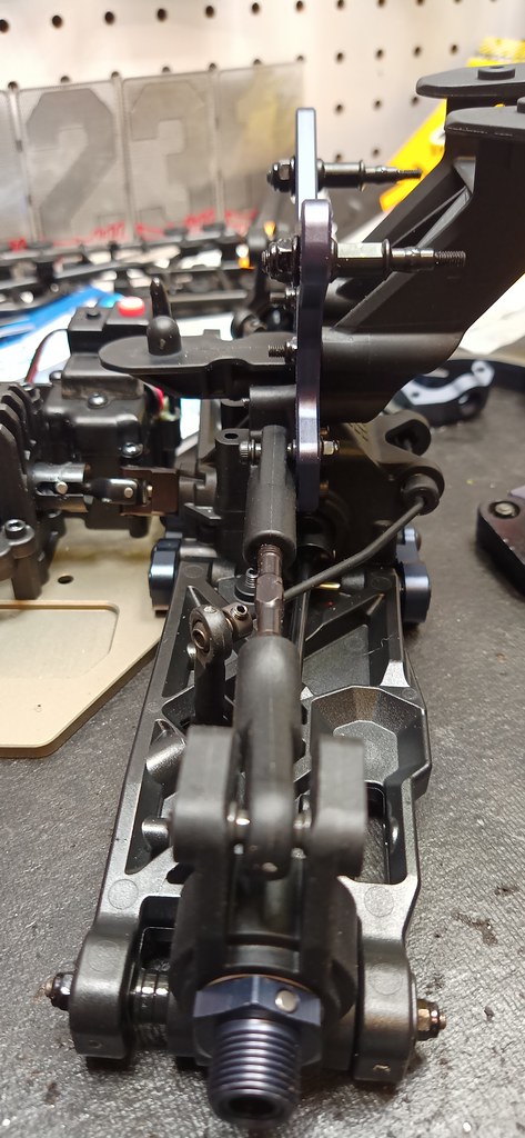
This is where I needed to complete the O BAG step where I find it necessary to use CA glue to lock in the M3 nut under the steering servo/arm
50349592282_29eeea74fd_b.jpg


O BAG complete:
50349433886_76f6d20f1f_b.jpg


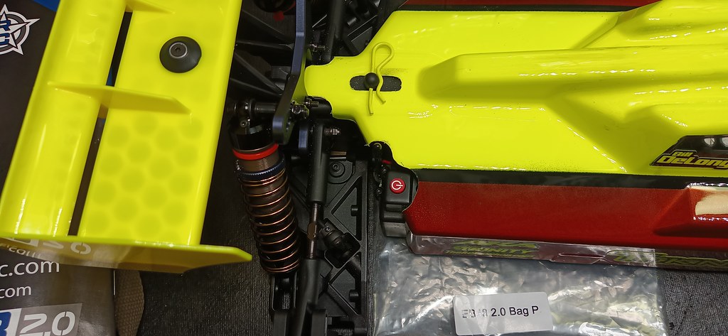
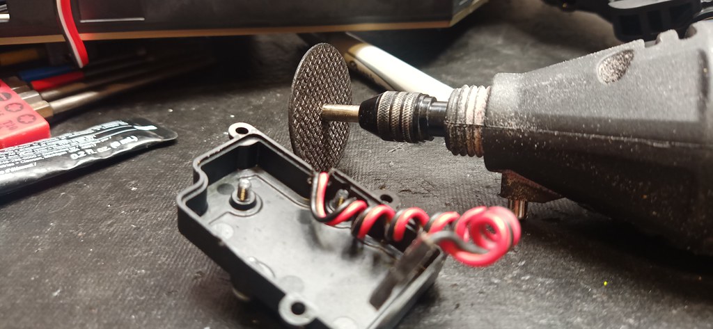
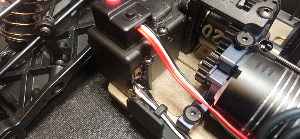
I will be using an MRT transponder which has the wiring come off the opposite direction from MyLaps which is what TEKNO designed the mount to be so I used my dremel to cut a notch out for the wiring to clear just below the lip of the seal:

50349655647_401791f086_b.jpg


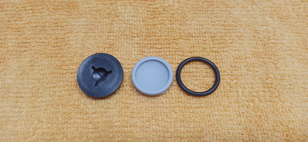
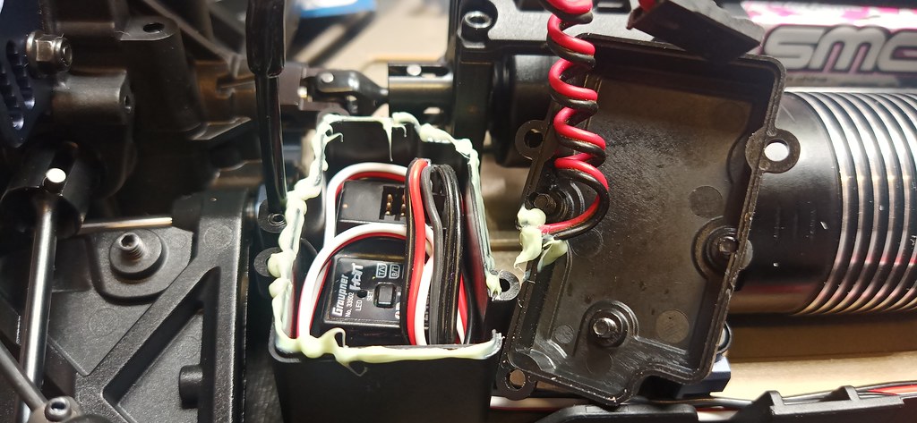
I like to keep my Rx looking new so I have applied grease around the lip of the cover to make it "dust proof"

50349663912_f1841628e3_b.jpg


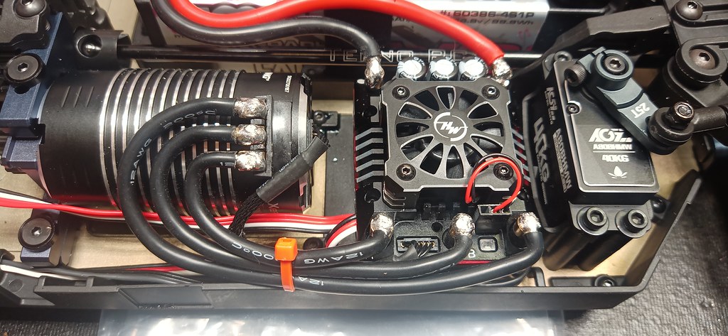
Next I soldered up the ESC like this:

50350068576_1cd3a38cda_b.jpg


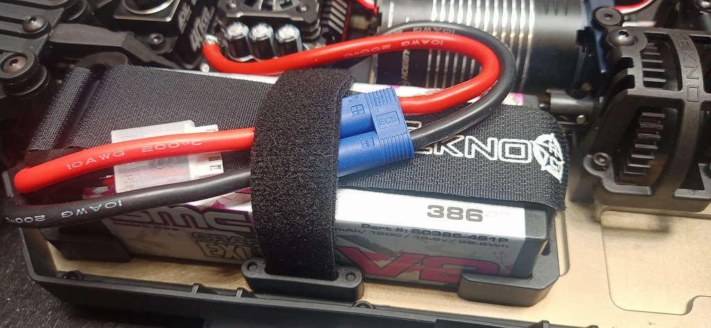
I decided to add my own 3/4" velcro strap which fits perfectly in the side slots of the battery tray, normally this wouldn't be necessary if I was using in-line bullets, but I opted for a budget pack with EC5 connectors and will need to strap this wiring down to keep the weight as low to the center of gravity as possible:
50350074401_24f9e48c8b_b.jpg


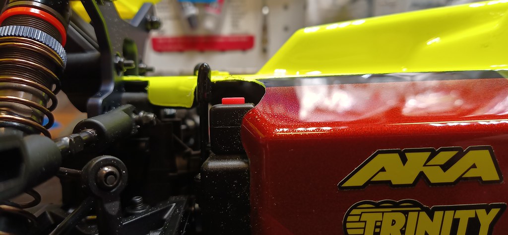
After I tested the electronics, I went back and filled the hole for the wiring into the Rx box with some E6000 to make it "dust proof", I really miss the old style block which did a better job of closing up the opening, the gap here is just absurd, I think there is a good opportunity here for a custom 3D printed Rx box that is waterproof.

50350069061_bf54769fa4_b.jpg


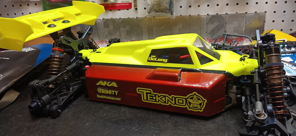
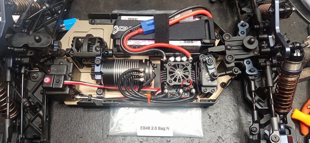
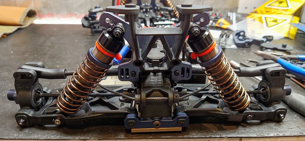
Final pic of the completed step :)

50349371028_172bc97764_b.jpg
 
When you mounted your motor did you use the lower mounting position?

Not sure on how much of a difference it makes but I figured since it had the two options, I would start with the lower position myself.
 
When you mounted your motor did you use the lower mounting position?

Not sure on how much of a difference it makes but I figured since it had the two options, I would start with the lower position myself.

Will you please elaborate how that works?

I just checked the manual and I don't see any mention of that feature. I just mounted the motor like its predecessors and didn't notice any option for motor height. I will say that the motor is practically flat on the chassis which is really nice, I've had issues in the past with the motor can splitting and have learned to create a support brace like this on the older platforms:

https://www.teknoforums.com/threads/build-review-sct410-3.1389/post-11936
 
Last edited:
So I picked up the remaining upgrades for my build at the track last night. I will update the OP with part numers/links in the OP under my recommended upgrades section.

50352368991_0c085210f6_b.jpg


Guys running the long links on the rear were having the plastic ball ends warp because the turn buckle isn't long enough to thread into place, so what they have done was swap out to the XRAY rear links which are longer and a lot beefier, the balls are exact same diameter and is a direct fit replacement:

50352527647_7e8dc984ca_b.jpg


It is worth nothing that XRAY has reversed the notch orientation on their turnbuckles so the side with the notch is counter clockwise thread, need to keep this in mind when mounting on the car:

50352527892_e1fd92a43f_b.jpg


Here are the shorter sway bar links (that come with the V2 long link kit from Team Thornhill) to get better clearance with the angled front links with the long link mod:

50352528227_50cc644c6b_b.jpg


I have decided to use zip ties to mark my rear shocks so I don't get them confused from the front shocks during rebuilds:

50352527842_2cc835b436_b.jpg
 
There are three holes in the motor mount. The upper one is oblong so you can slide up or down to use the either upper or lower hole on the mount.
Screen Shot 2020-09-17 at 7.10.11 AM.png
 
I had inadvertently used the lower hole on the mount, not realizing this would yield the LCG option, I can't think of any reason why anyone would want to use the upper hole other than if the motor they are using doesn't fit with the LCG option, I've seen some aftermarket fan mounts that wrap around the motor and that might require the upper hole perhaps?

Since you peaked my curiosity, I was curios to see how much of a difference in height it actually makes so I broke out my caliper to take some measurements from the bottom of the mount to the outer can diameter, this demonstrates the "depth" of the motor below the mount:

50352773112_26209385e9_b.jpg

You can see with the lower hole that the top of the motor is flush with the top of the motor mount after installed:
50351954333_b229913630_b.jpg


Then I experimented with the upper hole to see that it makes the motor sit 9.3 - 6.4 = 2.9mm higher!

50352623191_c529157ae6_b.jpg

50351934428_f81294d05d_b.jpg


I couldn't switch back to the lower hole on the mount fast enough, ha!

Anyway, thanks for pointing out this feature, good to know since it's not well documented in the manual.

@Matthew_Armeni
Any chance you can pull some strings to add a brief explanation in the manual?

*** I'm now tempted to drill a new hole in my motor mount for my SCT410 ;)
 
Last edited:
Now I need to check mine. I think I'll be on the upper hole as per manual. I thought I checked the lower hole and it didn't line up well. I'll have to check again. I guess this would make the can sit flush with the chassis?
 
Now I need to check mine. I think I'll be on the upper hole as per manual. I thought I checked the lower hole and it didn't line up well. I'll have to check again. I guess this would make the can sit flush with the chassis?

If you are using the 4268 can from HobbyWing, then yes it will sit flush on the chassis, but no guarantee this will be the same for all brands of motors which is probably why they gave multiple options... If you mount the motor high, I have found that the can will tend to crack unless you support it with bracing like I showed earlier in the link to my SCT410 thread.
 
Last edited:
Nope I'm on the lower hole and the top of the motor sits flush with the top of the motor mount.

Yup I'm using the 4268.

I have a couple of 4268 cans. Interestingly you can see the can seam on one of them. It's not cracking, but you can see the join.
 
Last edited:
We accidentally left a graphic out of the instructions showing which holes to use. The mount has the 2 mounting options so that when you're running 36mm motors you can lower them for better COG. You can also run a 42mm motor in this position for on-road applications. We do not suggest running a 42mm motor in the lower hole when running off-road. The chassis will flex and hit your motor which can cause a ton of issues.

1600396077341.png
 
Hmm that's good to know. I'll switch holes then, as I'm only off road and running a 42 can.

Not had any issues so far with the motor or the mounts but will inspect when I move it up.
 
Everything looks fine, but I can see where the motor and chassis have rubbed when flexed. Few scratches on can and chassis.

I guess too much flex in the chassis could put pressure on the can and the motor mount and cause the can to break as well anyway! I have all the chassis stiffeners on, but those that choose not to might run into problems quickly.
 
@Matthew_Armeni

Thanks for the update, I will be sure to share this info with locals in my area, some have already reported damaging the cans of their motors with the LCG motor mount already, which is ironic because I've already cracked a can on my SCT without the LCG option, go figure?

Capture.JPG
 
P BAG:

I like to CA glue the M3 nuts in the wing mounts, be sure to fasten a screw in place first to make sure the nut is properly aligned before gluing in place ;)

50355727291_41187bb86d_b.jpg


I have opted to trim the body around the antenna and switch for easy access and prefer color matched body clips to go with my paint scheme:
50355960707_68ae2eb357_b.jpg


Different angle for body clearance of the switch:

50356190242_4a57cc0ab1_b.jpg


She's all finished and ready to get dialed on my setup station :)

50355096828_3ae34e5de8_b.jpg
 
Last edited:
I am new to RC racing and bought a EB48 2.0 from Chris a few months back. I live in San Antonio and have been up to TH to practice a few times. I have not raced yet, my goal is to get around the track consistently before I sigh up. Anyway, I bought another kit and now that I have a better understanding I will build the new car and relegate the older one to parts or practice car.

I just found this forum and am excited to see your build/ learning and hopefully meet you at the track in the near future. I hope to learn from your thread the does and don'ts and so far this has been fantastic. Thanks for taking the time to help others ...

Cliff
 
@CliffP

Looking forward to meeting you at the track! Always a pleasure to help others out, sometimes it's easier to sign up and race to get more proficient simply because there are dedicated turn marshals where if you're just practicing solo, you might spent more time walking down the driver stand than actually driving, ha!

Slower is faster... if you keep wrecking on the same section of track, then drive that area slower until you get a feel for it, then you'll naturally drive faster once your consistency picks up. Also focus on holding your line, don't make any abrupt changes to your steering, slow and steady movements with both controls, just hold your line nice and smooth and faster drivers will get around you, don't worry about getting in someone's way, then as someone passes you, try to follow their line for a few turns which will help you get better fairly quickly.

Good Luck!
 
I've updated the OP with links to all the upgrades and modifications made for my build.

I found it necessary to trim about 0.5mm on one of the steering ball ends between the servo arm and the bellcrank, I needed 2 extra turns tighter in order to get the servo arm to align with the bellcrank (and have the ackermann bar perfectly centered) without having to adjust the sub trim (as a personal preference):

50356518033_337d5d445b_b.jpg
 
Last edited:

Recent Popular Liked

Back
Top