• Welcome to Tekno RC Forums! Are you a Tekno RC fan? If so you're in luck as you've have arrived to the biggest and best Tekno RC community.

    Come join our community and ask your questions, show off your Tekno RCs and share your experience!

MT410 Build -- Lots of Upgrades and Stuff

This site may earn a commission from merchant affiliate
links, including eBay, Amazon, and others.
Ha, this will only improve your soldering skills

Actually, I had it right after all. I copied the wiring I have on a MGM controller and didn't think about what it actually was. After checking into it that was a series adapter so it's fine.

The controller is rated for a minimum of 3S, so I doubt it would function on 2s.
 
I finally took my pile of wires, PCB and camera and did a little testing yesterday. tried some solderless connectors as this was just a test, and found that I'd have been better off soldering everything together. I spent more time trying to get proper contacts than anything else. Removed the solderless connectors, stripped the ends of the wires, twisted and taped.

The DVR works along with the camera and mic. I think I burnt out the GPS module as I (for some reason) was thinking it was rated at more than 5V and sent 12V into it. It got what we might refer to as hot. Ordered another three of those OSD GPS modules. I have at least one GPS module that might be compatible with this setup so I'll have to dig through my electronics stuff to find it. They all generate the same data, so I'd be surprised if it didn't work. Well, the data format could be a problem. Dunno. We'll see.

Now I just need to figure out how I want to package all this stuff up in a tidy little kit
to mount on the truck. That, and figure out how to change the aspect ratio on the camera. Hopefully its a modal setting, as I don't want to go back and change it every time. Why is 4:3 still the default on those things?

This looks a bit messier than it is as there are some extra wires I'd cut and left them there. But, there is a lot of wiring, no doubt about that.

2841
 
I found a GPS module that I can try. I've had this thing for several years, didn't have a particular project for it when I bought it. It was supposed to be a solid GPS device as I remember, with a high data rate. I'll have to dig into what voltage requirements it has. It was somewhere around $45 at the time.

2842
 
Not sure, but I think that GPS module works. I took a shot from a video and the GPS related fields show up. They're kinda blurred, but that's how they show up on the video. I'm hoping that is because there is no fix on the GPS signal. I have another GPS module for the OSD board coming on Thursday, so even if this one doesn't work it's not a big deal.

I'm located where I'll have to go for a walk to get a GPS lock. No way I'll get a GPS location in this building.

2843
 
I wanted to prove the OSD GPS unit I'd bought works, so I opened a window and pointed it toward the sky. Looks like it's functional. The camera image quality is kinda crappy. It's a cheapo generic I'd picked up for a little over $20. Wasn't expecting too much for that price, and it doesn't disappoint in that regard.

But, the Foxeer seems to be a better camera, and after thinking it had failed I pulled it and replaced it with the one in the video (turns out I had inadvertently put the FPV transmitter in a very low power range). Neither are 16x9 cameras, although they're presented as such in the eBay listings. Nonetheless, I did track down a few proper HD (well, they're *supposed* to be) cameras and will have one of them in a few days.

Here's a short clip with the on screen display from the GPS unit and the DVR/FPV transmitter.


I bought a FPV receiver that connects to your phone. I needed it for doing configuration on the cameras because you need a display to see the menu system. Cranked up the output wattage on the transmitter and it got nice and toasty. I think I'll put a heat sink on that thing, but I don't plan on using it at that output anyway. I'll be recording on a micro SD card on the DVR.
 
I received the two HD cameras, and they're a massive improvement all the way around regarding sound/video quality. They each came with a DVR and when I consider the setup I already had of $20-$30 cameras and then adding a DVR, weren't really any more expensive, but something I'm trying to figure out is how to get a GPS receiver connected to them. The new HD camera are also probably 40% smaller. Eventually, when I add mounts for the lights to the front cage mount, I potentially can add the camera and have it positioned right behind the bumper.

The new cameras use a cable that is considerably different than the single wire video output on the SD cameras, so there's no hacking on the connectors that will allow me to splice in a GPS on screen display. A single wire video output does exist, but the old DVR I have doesn't properly record HD output. It converts it back to a 4:3 scale.

There is, however, a few soldering pads on the DVR boards (which use the same processor, so they're very similar between the two cameras) marked RX, TX, GND, which appear to be for a serial connection -- which is a common method for signal feeds from GPS devices.

I did a little research on the processor on the boards, and see they're mentioned to be GPS/accelerometer capable, so I'm hoping that I can locate an input for a GPS signal. Hmmnn...well, actually, I'm taking a huge leap of faith in thinking that even if a GPS signal is applied, that it does anything with it.

Dunno if it's worth the effort. Those soldering pads are pretty small. A millimeter in diameter at most.

I'm thinking that the whole GPS/camera FPV/OSD thing is a bridge too far right now. I might be able to cobble something together, but I need to get this thing on the ground and give it a run. I absolutely want a FPV camera. I can work out the GPS stuff later.
 
I managed to mount the camera. It's not quite what I had in mind, but the plus on this is that I can incorporate it into the cage mount I'm using when I get around to adding the light mounts to it without too much effort when I print it again.

I initially planned on using screws to attach the camera mount to the cage mount, but that doesn't work out well unless you plan on having a hole to be tapped in the cage mount. I used a lightweight printing format where anything outside of the outer skin isn't solid. It has a 15% fill on the interior of the part. It's a honeycomb pattern or whatever I chose at the time. Once you get beyond a few layers of a millimeter or so, it's not something that can support a tapped hole. I could print solid, but typically with parts like this, there's no point in doing that. I didn't have any idea at the time I printed the cage mount I'd be needing to do this.

Anyway, I decided to come up with an alternate solution when the tapped holes failed. I simply looked at the plastic parts that came with the kit. I figured the parts that came with runners (the pieces attached to the parts themselves that were the byproduct of injection molding) would probably include a 3mm diameter section. I did find a section and am using that as a dowel more or less to guide the camera mount I printed onto the cage mount.


2949


I glued them into place with some CA glue.

Here's what the camera looks like mounted. I think it's not quite level, but it'll do for now.

2950


2951


It's not glued into place yet, but will be soon enough.

Now that I think about it, I'll hold off on gluing it until I get a shot of what the image looks like out of the front of the vehicle. I don't know what it will look like due to the bumper blocking part of its field of vision. I don't think it will be too bad, however.

I need to mount a small DVR board that the camera attaches to. It will be on the other side of the shock tower.
 
Uh...lots of fisheye like distortion on the image as the camera is set up now.

2952


Need to look into what settings might be available provide a more even image.

The good thing is that the bumper doesn't block too much
 
As I typically do, I decided to add some improvements to the camera mount. I've also created a few new problems with the improvements, but that's how the process goes.

I was going to mount the DVR board that the camera is connected to on the other side of the shock tower. I started looking at the connector that plugs into the DVR, and decided that trying to get that connected was going to be a fairly difficult task with the cage and everything else to deal with in the way. In addition to that, trying to get a micro SD card in and out of the DVR, or hitting the button to enable/disable recording wasn't going to be so easy either.

Decided to mount it underneath the camera mount I'd created. Designed some spiffy new features such as how I was going about actually attaching the camera to the mount, and protection of the lens when the bumper is compressed.


2968


Bear in mind that the two closer screws on the right are M2 size.

2969


And I also wanted a protective cover below the DVR


2970


Something I hadn't taken into consideration was the height of everything. We'll get to that in a moment. This shot is to show the stack hanging off the bottom of the camera mount -- it needs to be flipped over to be put on the truck.

2971


2972


The assembly is surprisingly strong. And also much too tall. There is interference between it and the bumper mount. I need to redesign to fit it all in there. I decided to remove the lower cover. Found there is still interference at the rear where the wires stick out of the board with the cage mount where this assembly is attached. Need to move the board forward.

The cover is way too thick, and the legs on it are probably 3mm too tall. I can reduce its overall height by probably 5mm, and perhaps I'll use flathead screws instead of the socket head cap screws. Can probably reduce the height between the board and the camera mount by another 5mm.
 
Just finished the latest revision on the camera mount. It's printing now. It reduces the height of everything assembled by a little over 10mm. Should be enough.

2975


And the cover for the DVR.

2976
 
Since I've got a few sets of 2S batteries, I need a parallel connector for them. Thought I'd make it myself.

View attachment 2792

That's 10 awg wire. I have plenty of EC5 connectors, and am getting used to soldering them.

Although they're not perfect all the time.

Blob!

View attachment 2793

Took a bit of effort with the solder wick to clean that mess up. I thought that I had honed my skills with solder wick recently, but I botched that one up a few times and took longer than it should have to get the solder off the connector.

Ended up with a good parallel connector. Worked out great! The tool I use to force the connectors into the housings is on the left. That thing makes it fairly easy to assemble them, and would be much more difficult without it. Supposedly you're supposed to use a hammer with it, but I use a vice to apply pressure. Works well and seems to be a better method for me. You can control the pressure and feel when the connector seats in the housing properly.

View attachment 2794
I see you have the soldering station I am thinking about getting. This will be my first time at soldering up the esc, motor and connectors. What temp to you set the soldering station at? Thanks!!
 
You're thinking of getting a Hakko FX-951? It's a great soldering station! I don't solder often and I've only had it for a matter of months now, but I like it. Heats up fast after it goes into power down mode. There's a switch in the holder that communicates with the controller. Works very well.

I had to turn it on as I couldn't remember exactly what temp I was using. 650 deg is what I was using on the 10ga wiring I was working on.
Thanks very much for the info. I'm in the last stages of my MT410 build and can't wait to get it up and running. Thanks again!
 
Nice build! I have some custom made Kydex mud guards if you are interested. They are wider than the ones Tekno makes and they don't interfere with suspension motion.
 

Attachments

  • MUD GUARD 1.jpg
    MUD GUARD 1.jpg
    166 KB · Views: 291
  • MUD GUARD 2.jpg
    MUD GUARD 2.jpg
    162.5 KB · Views: 314
  • MUD GUARD 3.jpg
    MUD GUARD 3.jpg
    163.7 KB · Views: 307
I did get into assembling the differentials too. Center diff is ready to go, whereas it took so much of the 100K diff fluid that there isn't any left for the front diff. And I don't have any 100K diff fluid here, so I had to order some. It'll be here on Saturday.

The reason the center diff took so much fluid is that I'm using a different diff cup. I ordered the M2C set.

Here's a comparison of the stock diff cup and a M2C aluminum version.

View attachment 2525

The M2C diff cup is supposed to hold 2X the amount of fluid, and seeing I used all the 100K fluid from my kit it appears that is accurate.

The build is pretty much as diff builds go -- I tried to make a mess. I probably should have cut down the nozzle to get more flow out of the bottle. Blew it out with too much pressure.

View attachment 2526

Luckily I avoided the mess.

M2C provides shims that isolate the spider gears from the aluminum cup. It prevents wear on the cup so it will last longer. Or that's what I think I read about it.

You can see the shims in this shot. It's kinda tricky getting installing everything with those shims. On the front/rear diffs I dabbed a little grease on the back of the spider gear. The shims would stick to it, which made for a much easier assembly. Otherwise, they constantly fall off.

View attachment 2527

I was trying to stick to the directions as closely as possible. I noticed the recommendation was to fill the diff cup to within 1mm of full. That's too much. Had to remove some.

I'm not quite done with the front/rear yet, but figure I'll have that done after work. I'll assemble the front diff with no fluid and soldier on.
I did the exact same thing. lol
 
I mentioned before that I didn't like the ESC mount I'd 3D printed, and decided that I'd redesign it to make it easier to mount and also mount the ESC on it. Where it is mounted doesn't leave much room for putting nuts on screws, so I decided to go with threaded inserts. It's much much easier to install and the ESC can be easily removed too.

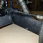
This is the base plate. I'm using the same screw pattern to mount it to the chassis as the original mount plate that comes with the MT410.

View attachment 2721

I used carbon fiber tubing for mounting the top plate to it. That was mainly because it was the size I thought I'd use and I had some here. I created a set of bosses on the piece and glued them in.

The clearance holes for a few bosses on the plastic side pieces on the chassis look a little ugly here, but it's not like they're visible when this thing is assembled. I also printed the piece that looks like a step here as it's impossible to print the part as a solid piece like that. I simply glued it on as well.


View attachment 2722

This is the top plate where the ESC is mounted. Designing it took a while. I haven't gotten into anything other than straight forward right angle design work with the modeling software I use, so this was more of a challenge. It came out ok.

View attachment 2723

View attachment 2724

This is the plate where the ESC is actually attached.

View attachment 2725

View attachment 2726

How the base plate is mounted in the chassis. I'll have glued it together as the whole ESC mount assembly before it's put into the chassis for good. This shot is to show how it's located.

View attachment 2727

Glued the top plate to the support rods.

View attachment 2728

View attachment 2729

Mounting the ESC to the its mount plate. There are four 2mm tapped holes in the heat sinks on both sides of the ESC, you can see the top set in this picture. I used the set on the opposite side.

View attachment 2730

Then that is mounted on the top plate of the assembly.

View attachment 2731

Mounted in the MT410.

View attachment 2732

View attachment 2733

Then the motor is added.

View attachment 2734

This is a much more functional design than the first one I came up with.

I removed the bullet connectors that were on the ESC and put an EC5 connector on it. That turned out to be more of a challenge than I was anticipating. You can't get any solder on the outside of the connector as it will interfere with the way it seats in the plastic EC5 housing. Also, the clearance on EC5 bullet connectors to the plastic housings are tight, to the point of which installing them is challenging. I ordered a tool that will be here next week for that, but printed up something similar today and used that to assemble the connector for the ESC. I went through several ideas on how to go about it. Took a long time.

I'm going to connect the basics and do a test to verify the motor/ESC work properly. I still have to figure out how to mount a FPV camera and the lights I'll be using. I'll be the only one around when running this thing so getting video isn't going to be something easily done. I got a camera and a GPS module and the component that adds the speed to the video. I might even run a front/rear camera setup.

This is impressive. Well done!

I’ve heard a lot of people have the same complaint about soldering EC5 connectors. Did I just get lucky? I found them to be the easiest connectors I ever soldiered. But I only did a handful. I just held them with a helping hands and melted some solder in there, tinned the wire, then melted it together. It was super easy for me. I think the most important part is making sure to not over fill the connector with solder.
 
I can attribute some of my difficulty in soldering to my lack of experience in working on larger gauge wiring. Most of what I've done is light gauge wiring and/or really small headers (like .04" spacing) And as you pointed out, I probably added too much solder to the connector. I tend to go overboard on things, and that's one where it will definitely make the job much more difficult.

As for pushing them into the connector, I actually put the assembly tool in a vise along with the connector to force it together. The fit is so tight that there's no way I can assemble them without some sort of force like that. It's pretty easy that way once I got the hang of it. You can feel the connector seat on the connector housing ring when it's in place.
 
As I mentioned in another thread, I have to do some wiring adjustment as I've run out of slots on the receiver I'm using. The BEC isn't plugged in and there aren't anywhere to connect it. heh.

I've begun to think about what might be next on the schedule once I get this completed (hopefully within the next few days, if not, after I get back from a trip).

I'd like to have something I can run in wet conditions. The way my MT410 is loaded up with electrical stuff there's no way I can run it in where there is water present. I'm not talking dunking it under water, but if it were to get splashed with a fair amount it would survive. It'll be a Tekno, but I haven't decided on the model. Might go 1/10 scale this time. Don't really have a problem with a used truck, either. Preferably a roller. Might be time to look through eBay.

Then again, I have plenty of spares parts for a ET48.3 too. And they're going to be dropping in value here in the not so distant future.
 
I finally got everything in place well enough to take the MT410 out and run it. After putting everything together I found the camera/GPS was't working. I didn't care. I was tired to messing around with wiring and just wanted to get the truck out for a break in run.

A friend and I went to an area next to the East River along a bike path running the length of Manhattan. It isn't what I'd consider a particularly good place for the first run of a RC truck. Too much crap to run into such as park benches and actual ship mooring bollards -- big ones. The area wasn't particularly wide, either.

Before I get into the things that happened I want to say the truck itself is fine. Nothing on the truck that is Tekno produced broke. It drove great, handled very well and I never felt it was going to roll over at any point. The traction wasn't great as there was plenty of dust/sand on the cement surface so it just slid around. I have an idea of another space where I can run the truck that is a much wider area and will allow me to see what its handling characteristics are like at speed.

Now for the complications. The pinion gear shifted toward the motor on the shaft and managed to disengage itself from the spur gear. That happened on the first set of batteries, although we did get quite a bit of run time out of it.

The second complication is one that's going to take a bit of work to deal with.

I completely cracked the front roll cage mount in half. I smacked one of the aforementioned mooring bollards pretty much head on -- at not too high a speed a few times, but enough to push the bumper into the camera mount, which in turn broke the two pins it was mounted on and was forced up into the light housing with enough force to split the cage mount in half.

20200101_181727_HDR.jpg


And with the help of a plastic fork holding the cage up.

20200101_183710_HDR.jpg


I'll take it apart within the next few days and get some more detailed pictures of the cage mount. The rear cage mount seems to be fine.

I used PLA filament as the material for the mount, and it appears I need to revisit that decision. While PLA is reasonably strong (independent of what you'll read online in forums, if you look up the specs it's a very strong plastic) but it is also somewhat brittle, and won't stand up to impacts as well as some other filaments. In hindsight, that makes for a poor choice of material for this project.

I was planning on printing another cage mount where I incorporated the light housing, which are mounted in the gray piece at the front of the truck hanging down, into a single part. Maybe I'll include the camera somehow, not sure at the moment. The light housing is printed with TPU filament, which is a strong, but also flexible filament that can withstand impacts much better than PLA so I might consider that instead.

It was fun while it lasted, though. I'm hoping to maybe get another cage mount printed this weekend.
 

Recent Popular Liked

Back
Top