• Welcome to Tekno RC Forums! Are you a Tekno RC fan? If so you're in luck as you've have arrived to the biggest and best Tekno RC community.

    Come join our community and ask your questions, show off your Tekno RCs and share your experience!

MT410 Build -- Lots of Upgrades and Stuff

This site may earn a commission from merchant affiliate
links, including eBay, Amazon, and others.
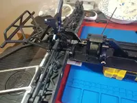
Oh boy, did that first vinyl chassis protector turn into a trainwreck! So for all of you out there reading my build thread, don't cut the vinyl to form then try to apply it to the chassis. That will not work. Or not as easily, anyhow.

Threw that out, cut a sheet a little larger than the chassis, applied it and cut the form from the chassis itself. Worked *much* better.

2566


2567


2568


There are a few imperfections in the vinyl wrap itself, such as a crease line running across it, and a few air bubbles. I can take care of the air bubbles, and I don't really care about the crease.

Wasn't sure if I was going to do the top of the chassis plate. I think I'll do that as well. This was pretty easy. Ya can't have people point out that your chassis plate isn't carbon fiber when they look at one side, then the other and figure it out!
 
I decided to add another layer of protection on top of the vinyl wrap. I bought some 3M paint protector that I wanted to try. I can't find the post now, but someone had mentioned it as a possibility when the vinyl protector was being discussed. Whoever that was, thanks for the suggestion!

I had the bright idea that I would be able to use a hole punch to cut the holes on the countersunk screw holes. So I bought a set! They look decent enough.

2608


I applied the paint protector over the vinyl, and this is what I ended up with.

2609


2610


That stuff is much tougher than the vinyl wrap. Over time I'll see how it holds up, but I'd guess it will take a beating. It's much more difficult to cut than the vinyl, and probably 3X - 4X the thickness too...which I suppose would pretty much explain some of the difficulty in cutting it.

The way it adhered to the vinyl shows, as it has funky lines and whatnot. It's flat without any air pockets. That's how it looks and I suppose I don't really care about that. When I do this again I'll forgo the vinyl and apply it right to the chassis.

The hole punch idea was a complete and total failure. I could have sharpened the hole punch, but getting it centered over the hole proved challenging, so I broke out the Xacto knife set and did it manually. That took some time, and I'm happy with the results.

2611
 
Last edited:
I then got back to the assembly.
2612


2613


Didn't have any problems. Everything went together as it should.

2614


2616


I ran a tap into the screw holes on the gearboxes that are used to mount the front and rear assemblies to the chassis. I didn't tap to full depth. Made starting the screws much easier.
 

Attachments

  • 20190501_215407_HDR.jpg
    20190501_215407_HDR.jpg
    136.5 KB · Views: 396
Got some more work done. I built the shocks and as I tend to do, made a mess. Dropped both rear shocks from a few setup blocks that I was using as a shock setup station -- which I might add went well until I opened a drawer below where they were hanging off the side of a counter, and promptly knocked both clear of their perch.

700wt shock oil all over the floor is a mess.

And it also left me perilously close to not having enough shock oil left to build the rear shocks. I had just enough, nothing to spare.

Finished off putting them together and then installed the front shocks with a M2C shock tower brace.

2617


I decided to install the M2C 'Go Big' kit that have. Found I'd bought a short rear brace from them that I'd installed previously that was now not needed, so I removed it and got started.

And ran across a problem where the center brace that I had installed doesn't line up with the M2C rear brace.

2618


The screw hole in the tab at the front of the rear brace does not line up with the tapped hole in the center brace.

2620


I must be missing something here. Everything else lines up as it should. The holes mounting it to the rear gearbox are lined up correctly, and the clearance holes for the heads of the socket head cap screws holding the diff top plate are lined up too.

2619


So I started thinking that perhaps there is a mismatch between the the center brace and the rear brace as they were from two different manufacturers?

I'd bought enough stuff that I really wasn't sure the specifics of what I bought where, and who produced them. After some digging through email I found that the center brace is a M2C product as well. I purchased it directly from M2C.

m2c6905 TEKNO ALUMINUM SOLID CENTER BRACE

Well, that must not be the problem. Started looking into the 'Go Big' kit, thinking I must have bought the wrong one.

Dug through some things, found the label from the packaging,and then ran a search on the P/N.
Turns out that M2C6970 is the proper kit for the MT410.

Looked at the center brace. There's only one way to install it properly, as the screw holes won't line up if you try to put it in rotated 180 deg.

I'm going to do some research to see what other installs of these components look like.
 
i think you have it upside down. and you need to leave the other brace in place, and remove the plastic top cover
 
Turns out I had it on upside down.

I'd laugh, but I'm just kinda annoyed right now.
 
@Blairw Hey, thanks! I did just figure that out. I suppose I'd read a bit on other rear braces, and I'm not sure if it was this particular model or not, had a clearance hole for a bolt that was the weak point on the brace. I've read a ton online over the last few months, and can't really remember. But, it planted the idea in my head that those holes should line up.

That does leave me wondering what the use of that tapped hole is.

Something that would go a long way toward solving problems like this is if the manufacterers would put a few pictures up of what the parts look like when assembled. Direct replacement parts aren't an issue, but the ones that are add ons such as this rear brace kit it would provide some clarity and eliminate a lot of frustration. Hot Racing has some as I recall, but most do not.
 
M2C6970 M2C Tekno MT410 "Go Big" Rear Tower/ Chassis Stiffiner Kit

M2C6973 TEKNO MT 410 REAR HORIZONTAL BRACE

Hopefully this will help someone else someday when assembling these parts.

2621


Glad that little experience is over.

I was just thinking, that I didn't swear at all while trying to figure that out. That's the mature, new me. heh.

I also forgot to add the washers that TBuggy suggested on the rear chamber links. I'll do that now.
 
Some more shots of the 'Go Big' brace kit.

2628


2629


2630


And I added the shocks. I picked up the aluminum shock caps, titanium rods, and aluminum cartridge caps on both the front and rear.

2631
 
Something I should mention is that the rear tower brace (m2c6705 TEKNO REAR SHOCK TOWER BRACE V2 MODEL) does not fit in the plastic piece properly. There is a contour that is molded into the plastic piece that prevents the brace from sitting flat against it. I broke out the files and removed material to allow for the brace to fit properly.

I have no idea as to why this image is rotated 180 deg when I upload it.

Anyway, in this image,just above the clearance channel for the shock mounts is where I had to remove material.


2634


The brace now fits and lies flat against the plastic piece.

2635
 
And another step.

2636


And I'm going to have to come up with a solution for mounting this octopus of an ESC. I hadn't really thought about it so much, although it was always in the back of my mind. I'll add the tray on the other side and mount the motor then see what might work.

2637
 
Finished installing the side trays, and pretty much have the chassis done. Have a cover to add and a few items yet, but overall it's pretty much done.


2639


Had a set of Road Rage not being used, figured I'd put them on for now. This will be run in the city for the most part, so street/concrete will be what I mainly use it on. I have a set of SRC Road Crushers that I'll probably put on it.

2640


I had to grind down the length of the screws that attach the motor mount. If they're too long, they intrude into the area where the air pump fins are on the motor,preventing it from spinning. I figure I took off about 1.2mm.

And the other side.

2641


The battery is a SMC 6S 5400 mAh True Spec Premium. I haven't bought other batteries for this truck yet, but figure I'll get at least two others, Probably a 4S similar to this one. I screwed up on the order for this battery as I ordered a 4S at the time and rushed through it. I found that I'd selected a 9200 mAh 4S as opposed to the 5400 I was intending to buy. It's kinda big. As in too big to fit in the battery tray for this truck. Anyone interested in it, I'll give them a good deal.

I found since there's no ESC being mounted on my truck where they normally are located I have three mounting holes to work with for the mount I will be 3D printing for my ESC. It will be just above the motor and at a 45 deg angle to the chassis. I plan on printing a base plate, then use some carbon fiber tubing (4 pieces) to mount the plate that the ESC is attached to. I have some flexible plastic that I've used previously that I believe will make for a good mounting plate. It could absorb some of the vibrations. Or if that doesn't work ABS will probably be the next step.
I'm also thinking about making a roll cage. Again, using carbon fiber tubing and 3D printing the joints. Most likely won't run a body until perhaps I take this to Wisconsin to visit some friends. It'll get some bashing at that time.

Hah! I found that the 9200 mAh battery, while it doesn't fit in the standard battery compartment, it does if you lie it over the plastic piece that retains shorter batteries. It's just barely short of the spur gear, but after strapping it in, it feels secure. Might work for just running around on pavement.
 
Sainsmart just announced a new desktop CNC router. I've been looking at them through the last few months, as that would enable me to greatly expand what I can make (and accuracy too). I've started work on a carbon fiber battery tray for my Gorillamaxx G2R, doing most of the work by hand. It's very, very time consuming to work carbon fiber by hand.

Sainsmart makes a big deal about that CNC router being compatible with Mach3 software for controlling the machine. Eh, I'm not a Windows person so I don't care about that. There's a Linux based controller software named LinuxCNC that I'd probably use instead.

I'll do some investigating to see what else is out there for desktop CNC type gear. I'm sure I'll buy one sometime soon.
 
I decided to see how well a VG racing roll cage for a E-Revo fits on my MT410.

2652


2653


It's just sitting on top of the shock towers. I would have to fabricate some sort of a set of mounts for it.

But, at a glance, it has potential. I was thinking of making a custom one from carbon fiber tubing and 3D printed joints, but that would take a long time and I don't want to wait. I could 3D print some mounts and have some protection without the need to buy a body for this thing, or not right away, anyhow.

It definitely has potential!
 
I 3D printed a mount for the ESC I'm using. I had thought about the design and changed my mind from what I was thinking of doing where I'd use four carbon fiber tubes to connect a base that was attached to the chassis with a plate on which the ESC is mounted. That might have been the better choice. What I have works, but it's very difficult to mount the ESC to it (small screws in a fairly inaccessible place) or even mount it to the chassis. The motor needs to be removed.

Nonetheless, here it is on the printer as it is cooling down.

2655


Then a few shots of it after I'd hacked some clearance on it for various items on the chassis where there was interference.

2656


2657


The ESC is held on with 2mm screws via tapped holes in the heat sinks. You can see the set that is on the opposite side of the ESC in the shot above. 2mm doesn't seem that small, but when you're trying to put screws into them and tighten them they seem tiny -- especially when they're located in a fairly inaccessible location.

Here's what it looks like when installed.

2658


2659


2660


2661


It's even difficult to get the connectors to the motor connected.

Then I realized I didn't solder on the EC5 connector for the battery, so I'll be doing that while it's installed. Not that big a deal, though.

Overall I'm not really happy with how that ESC mount turned out. It works, but it definitely makes you not want to disassemble it.

For the time being it's good enough.

I'm going to figure out how to mount the cage I mentioned a post or two ago. I need that with this ESC hanging out in the wind. I'll print mounts up and use the holes for the body mount posts to anchor it. Thinking TPU filament, as it would provide some flexibility.
 
I was able to come up with a way to mount the E-Revo roll cage on my MT410. It works, looks a little hokey, and I'm not altogether happy with it, but it's functional at this point.

I used the square holes where the posts for the body mount go to anchor the cage mounts. I haven't put any screws in them yet.

2677


The only part that I really have any doubts about is the rod on the bottom of the mounts that attaches the cage to the shock towers. Overall, I think this will take a decent hit. I used TPU filament, which is fairly tough and flexible as well. A hit will be dissipated across the four posts rather than one where a rigid mount would take the brunt of it. A shearing action could be a problem, but not really any more so than had I used a stiffer plastic.


2678


2679


2680


2681


I have some minor trimming to do on the parts to get a better fit, but for the time being it's good enough.

There's two concepts I have about that roll cage. One is the way it's mounted allows it to dissipate an impact, which is what I have now. The other is that it will be mounted in a way that's it adds to the structural integrity of the chassis. That would involve a more structurally sound plastic.

I have though about coming up with a set of mounts that use the method the cage was mounted on an E-Revo, which involves bars running side to side on the front/rear used in a clamping action on the body post towers. Can't do it the same way here, but I can print something that will provide that clamping surface.

I also bought some carbon fiber shock towers. Haven't installed them yet. Those will offset the added weight of the cage. Ordered a T-Bone Racing wheelie bar as well.

I wasn't quite on my game when printing these parts. Made a rookie design mistake once, and twice I printed the old version of the part I had just redesigned.
 
Came up with a much better design for cage mounts. I 3D printed the rear one and it seems like it should do the job. I haven't cleaned up the part at all, so it looks a little ratty, but I like it.

2682


I have to print another one as the center to center on the mounting holes for it are wrong. Apparently I didn't read the memo on measuring twice, cut (or in this case, print) once.

2683
 
I finally finished the roll cage mounts. Came up with a design that I like and doesn't look awful. This is a much stronger design as well.

I put it all together and didn't take any pictures of the parts themselves. It's actually kinda difficulte to get good pictures of black printed parts anyway, so I took images from the 3D models I created to print them.

The mounting bar on the roll cage was at what appeared (guesstimate) to be roughly a 5 deg angle, so I created the angle on the part and made the screw holes perpendicular to that surface.

I'm still getting used to FreeCAD. It's taken time to get used to its functionality. From a parametric standpoint I find that simple changes usually aren't a problem, but if the change affects other features it can be hit or miss if it can handle it. Sometimes you have to strip out fillets and merges then rebuild them after the change.

These are fairly simple parts overall. I'll get more into truly 3D work as my skills improve.

Front:

2691


Rear:

2692


And some pictures of the parts installed.

2693


2694


2695


2696


I like how that E-Revo roll cage fits. It worked out well.

I do want to build a cage out of carbon fiber tubing. That would reduce the weight quite a bit. That's a future project.

And I added a TBR wheelie bar.

2697
 
I mentioned before that I didn't like the ESC mount I'd 3D printed, and decided that I'd redesign it to make it easier to mount and also mount the ESC on it. Where it is mounted doesn't leave much room for putting nuts on screws, so I decided to go with threaded inserts. It's much much easier to install and the ESC can be easily removed too.

This is the base plate. I'm using the same screw pattern to mount it to the chassis as the original mount plate that comes with the MT410.

2721


I used carbon fiber tubing for mounting the top plate to it. That was mainly because it was the size I thought I'd use and I had some here. I created a set of bosses on the piece and glued them in.

The clearance holes for a few bosses on the plastic side pieces on the chassis look a little ugly here, but it's not like they're visible when this thing is assembled. I also printed the piece that looks like a step here as it's impossible to print the part as a solid piece like that. I simply glued it on as well.


2722


This is the top plate where the ESC is mounted. Designing it took a while. I haven't gotten into anything other than straight forward right angle design work with the modeling software I use, so this was more of a challenge. It came out ok.

2723


2724


This is the plate where the ESC is actually attached.

2725


2726


How the base plate is mounted in the chassis. I'll have glued it together as the whole ESC mount assembly before it's put into the chassis for good. This shot is to show how it's located.

2727


Glued the top plate to the support rods.

2728


2729


Mounting the ESC to the its mount plate. There are four 2mm tapped holes in the heat sinks on both sides of the ESC, you can see the top set in this picture. I used the set on the opposite side.

2730


Then that is mounted on the top plate of the assembly.

2731


Mounted in the MT410.

2732


2733


Then the motor is added.

2734


This is a much more functional design than the first one I came up with.

I removed the bullet connectors that were on the ESC and put an EC5 connector on it. That turned out to be more of a challenge than I was anticipating. You can't get any solder on the outside of the connector as it will interfere with the way it seats in the plastic EC5 housing. Also, the clearance on EC5 bullet connectors to the plastic housings are tight, to the point of which installing them is challenging. I ordered a tool that will be here next week for that, but printed up something similar today and used that to assemble the connector for the ESC. I went through several ideas on how to go about it. Took a long time.

I'm going to connect the basics and do a test to verify the motor/ESC work properly. I still have to figure out how to mount a FPV camera and the lights I'll be using. I'll be the only one around when running this thing so getting video isn't going to be something easily done. I got a camera and a GPS module and the component that adds the speed to the video. I might even run a front/rear camera setup.
 
It turns out the MGM 14063-3 ESC I have doesn't have a BEC. I have a few Castle BECs not being used so I'm set there. Just have to go about soldering some wires to the battery connectors on the ESC. Then solder on connectors so the BEC can be removed/replaced if needed.

MGM also recommends an anti-spark connector for batteries 6S and above, so I'll be doing some more soldering there. I only have one 6S as of now, but plan on at least one more. I need a few more 4S batteries too.

It took some time to track down the manual for the ESC too. MGM doesn't make it readily obvious as to where they're available.

Getting close to having a truck on the road.
 

Recent Popular Liked

Back
Top